Table of Contents
Table of Contents
Introduction
In modern electrical systems, efficiency and stability are everything. Engineers and students alike often encounter the term Reactive Power Converter, but what does it really mean, and why is it so important? At its core, a reactive power converter is a device or system designed to manage the flow of reactive power—an invisible but critical component of electricity that keeps voltages stable and equipment running smoothly.
Unlike active power, which does the “real work” of lighting bulbs or powering motors, reactive power supports the system by maintaining voltage levels. Without it, grids would collapse under stress, and industrial equipment would fail to operate correctly. This article explores the formulas, calculators, requirements, and applications of reactive power converters, while also answering common questions like how reactive power is generated and why it matters for voltage stability.
Fundamentals of Reactive Power
Active vs Reactive Power
Electricity has two main components:
- Active Power (P): Measured in watts (W), it performs useful work.
- Reactive Power (Q): Measured in volt-amperes reactive (VAR), it sustains the magnetic and electric fields needed for machines to function.
A simple analogy: active power is like the forward motion of a bicycle, while reactive power is the balance that keeps the bike upright. Without balance, forward motion is impossible.
How is Reactive Power Generated?
Reactive power is generated whenever alternating current (AC) flows through inductive or capacitive elements such as motors, transformers, or transmission lines. Inductors “consume” reactive power, while capacitors “supply” it. A Reactive Power Converter balances these flows to maintain system stability.
Voltage and Reactive Power Relationship
Voltage stability is directly tied to reactive power. If reactive power is insufficient, voltage drops; if it’s excessive, voltage rises. Converters act as regulators, ensuring the system stays within safe operating limits.
Reactive Power Converter Basics
Definition and Core Function
A Reactive Power Converter is a device that dynamically adjusts reactive power in a system. It can either absorb or inject VARs to stabilize voltage.
Types of Reactive Power Converters
- Static VAR Compensators (SVCs): Use thyristors and capacitors/inductors.
- Synchronous Condensers: Rotating machines that generate or absorb reactive power.
- STATCOM (Static Synchronous Compensator): Advanced converters using power electronics for fast response.
Key Components and Working Principle
Most converters include:
- Power electronic switches
- Capacitor banks
- Inductor coils
- Control systems for real-time adjustment
Reactive Power Converter Formula & Calculations
Standard Formula
Reactive power is calculated as:
Q=V×I×sin(ϕ)Q = V \times I \times \sin(\phi)
Where:
- QQ = Reactive Power (VAR)
- VV = Voltage (Volts)
- II = Current (Amps)
- ϕ\phi = Phase angle between voltage and current
Step-by-Step Example
If a motor operates at 230 V, 10 A, with a power factor angle of 30°:
Q=230×10×sin(30°)=1150 VARQ = 230 \times 10 \times \sin(30°) = 1150 \, VAR
Reactive Power Converter Calculator
Online calculators or Excel-based tools allow engineers to input voltage, current, and power factor to instantly compute reactive power. For a quick and accurate calculation, you can try our Reactive Power Converter Free Online Tool.
If you’re working with structured data or need to inspect power system configurations in JSON format, our Free JSON Viewer and Formatter can help you visualize and debug your inputs instantly—especially useful when integrating converter parameters into simulation tools or web-based calculators.
Reactive Power Control in Steady State
In steady-state operation, the control of reactive power is closely tied to the active power being transmitted. To simplify analysis, the equations are often expressed in per-unit (p.u.) quantities, which normalize values against base units for easier comparison and scaling.
Base Quantities and Definitions
- Base Converter Voltage
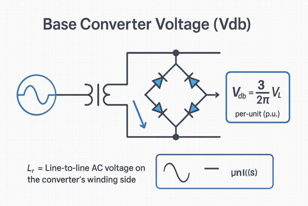
Vdb=32π×VLV_{db} = \frac{3\sqrt{2}}{\pi} \times V_{L}
where VLV_{L} is the line-to-line AC voltage on the converter’s winding side.
- Base DC Current
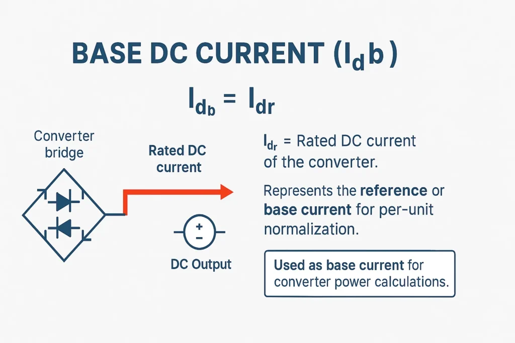
Idb=IdrI_{db} = I_{dr}
where IdrI_{dr} is the rated DC current of the converter.
- Base DC Power
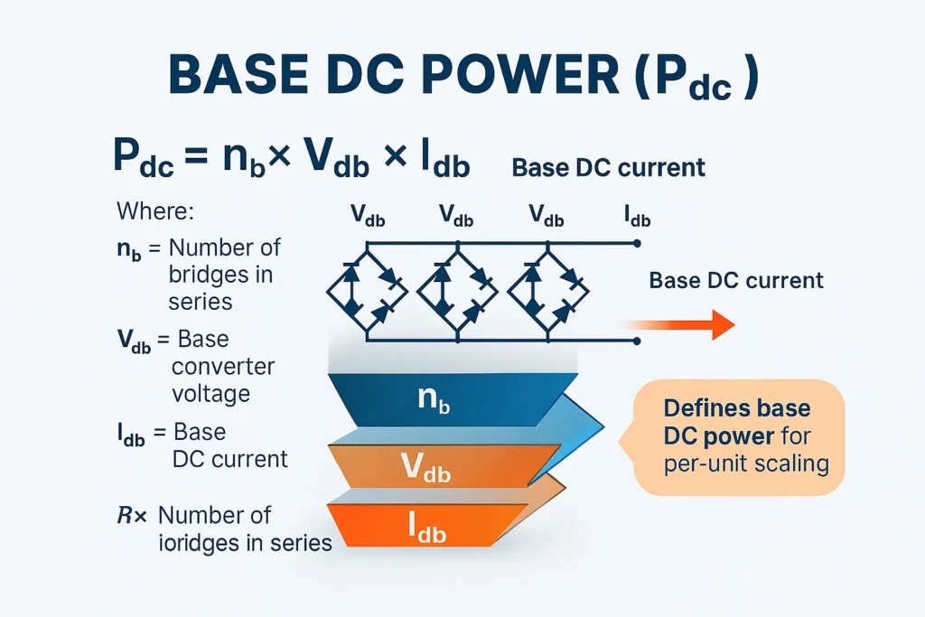
Pdc=nb⋅Vdb⋅IdbP_{dc} = n_b \cdot V_{db} \cdot I_{db}
where nbn_b is the number of bridges in series.
- Base AC Voltage
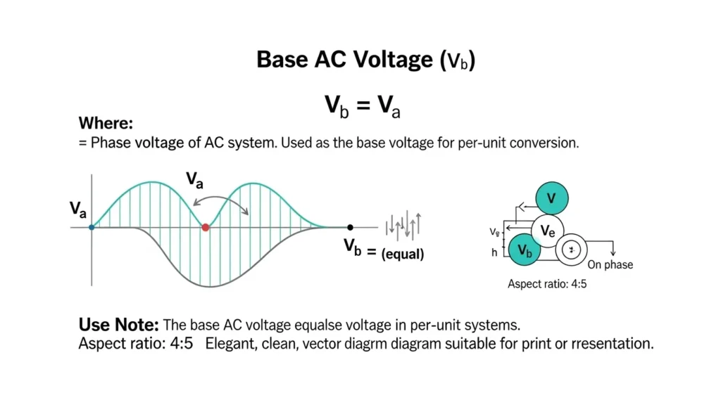
Vb=VaV_b = V_a
where VaV_a represents the phase voltage.
- Base AC Power
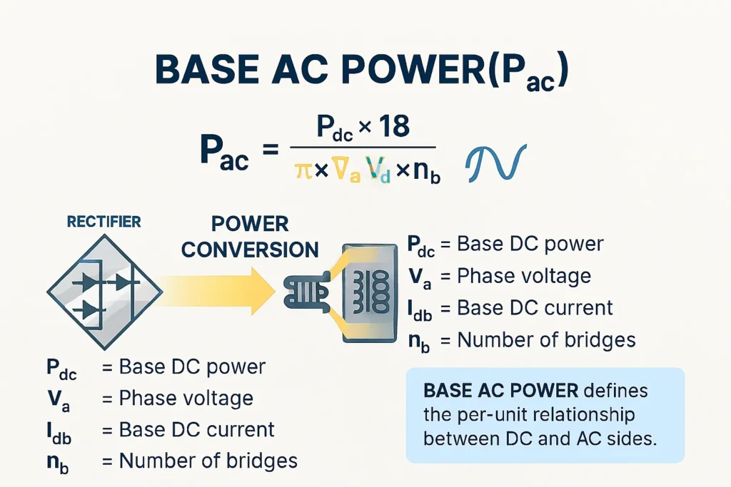
Pac=Pdc18π×Va×Idb×nbP_{ac} = \frac{P_{dc}}{\sqrt{18}\pi} \times V_a \times I_{db} \times n_b
Interpretation
These relationships show how reactive power control in steady state depends on the balance between DC and AC side parameters of the converter. By defining base values for voltage, current, and power, engineers can:
- Normalize system equations for easier comparison across different converter ratings.
- Predict how changes in line voltage or DC current affect reactive power flow.
- Ensure that converters operate within safe limits while maintaining voltage stability.
In practice, steady-state control allows the converter to inject or absorb reactive power as needed, ensuring that the grid remains balanced even under varying load conditions.
Applications and Requirements
Reactive Power Requirements in Power Systems
Every grid has minimum reactive power requirements to maintain voltage stability. Converters ensure compliance with these standards.
Industrial Applications
- Steel plants
- Renewable energy integration (wind/solar)
- Data centers
- Transmission networks
Benefits of Using Reactive Power Converters
- Improved voltage stability
- Reduced transmission losses
- Enhanced equipment lifespan
- Lower energy costs
Reactive Power Consumption & Optimization
Causes of High Reactive Power Consumption
- Inductive loads (motors, transformers)
- Poor power factor
- Long transmission lines
Methods to Reduce Reactive Power Losses
- Installing capacitor banks
- Using synchronous condensers
- Deploying STATCOMs
Case Study: Reactive Power Optimization
A wind farm in Germany reduced transmission losses by 15% after installing STATCOM-based reactive power converters, proving their real-world value.
FAQs For Reactive Power Converter
What is the difference between active and reactive power?
Active power does useful work, while reactive power sustains voltage and fields.
How do you calculate reactive power requirements?
By using the formula Q=V×I×sin(ϕ), Q = V \times I \times \sin(\phi), or with a reactive power calculator.
Why is reactive power important for voltage stability?
It prevents voltage collapse and ensures reliable grid operation.
Can reactive power be converted into active power?
Not directly—reactive power supports active power but doesn’t perform work itself.
Conclusion
The Reactive Power Converter is more than just a technical device—it’s the backbone of modern electrical stability. By managing reactive power, converters ensure that industries, homes, and renewable energy systems operate efficiently and safely. From formulas and calculators to real-world applications, understanding reactive power is essential for engineers and students alike.
As grids evolve toward renewable integration and smart technologies, reactive power converters will only grow in importance. Investing in knowledge today ensures a more stable, efficient, and sustainable energy future.


Pingback: Free JSON Viewer and Formatter Online | Format Instantly